Toggle Nav 
Search
General heating and cooling duties.
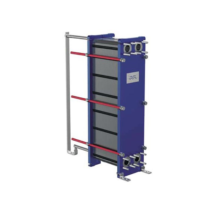
The plate heat exchanger consists of a pack of corrugated metal plates with portholes for the passage of the two fluids between which heat transfer will take place.
The plate pack is assembled between a fix frame plate and a movable pressure plate and compressed by tightening bolts. The plates are fitted with a gasket which seals the interplate channel and directs the fluids into alternate channels. The number of plates is determined by the flow rate, physical properties of the fluids, pressure drop and temperature program. The plate corrugations promote fluid turbulence and support the plates against differential pressure.
The plate and the pressure plate are suspended from an upper carrying bar and located by a lower guiding bar, both of which are fixed to a support column.
Connections are located in the frame plate or, if either or both fluids make more than a single pass within the unit, in the frame and pressure plates.
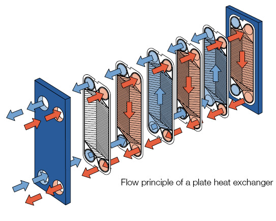
Channels are formed between the plates and the corner ports are arranged so that the two media flow through alternate channels. The heat is transferred through the plate between the channels, and complete counter-current flow is created for highest possible efficiency. The corrugation of the plates provides the passage between the plates, supports each plate against the adjacent one and enhances the turbulence, resulting in efficient heat transfer.
| Pressure vessel codes, PED, ASME, pvcALS™ Mechanical design pressure (g) / temperature | |||
|---|---|---|---|
| FM | pvcALS™ | 1.0 MPa / 180°C | |
| FM | PED | 1.0 MPa / 180°C | |
| FG | pvcALS™ | 1.6 MPa / 180°C | |
| FG | PED | 1.6 MPa / 180°C | |
| FG | ASME | 150 psig / 320°F | |
| FD | pvcALS™ | 2.5 MPa / 180°C | |
| FD | PED | 2.5 MPa / 180°C | |
| FD | ASME | 300 psig / 320°F | |
| CONNECTIONS | |||
| Pipe Connections | |||
| Straight threaded Size 50 mm ISO G2", NPT 2" | |||
| Threaded inlet port Size 50 mm ISO G2" | |||
| Straight threaded Size 65 mm ISO G2 1/2", NPT 2 1/2" | |||
| Flange Connections | |||
| FM | pvcALS™ | Size 50 / 65 mm | DIN/GB/GOST PN16, ASME Cl.150 |
| FM | PED | Size 50 / 65 mm | DIN PN16, ASME Cl. 150 |
| FG | PED | Size 50 / 65 mm | DIN PN16, ASME Cl. 150 |
| FG | pvcALS™ | Size 50 / 65 mm | DIN/GB/GOST PN16, ASME Cl. 150 |
| FG | ASME | Size 50 - 65 | ASME Cl.150 |
| FD | PED | Size 50 / 65 mm | DIN PN40, ASME Cl. 300 |
| FD | pvcALS™ | Size 50 / 65 mm | DIN/GB/GOST PN40, ASME Cl.300 |
| FD | ASME | Size 50 / 65 mm | ASME Cl. 300 |
Maximum heat transfer surface 102.0 m2 (1097 sq.ft)
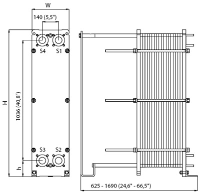
| Measurements mm (inch) | |||
|---|---|---|---|
| Type | H | W | h |
| TL6-FM / PED / pvcALS™ | 1264 (49.8") | 320 (12.6") | 137 (5.4") |
| TL6-FG / PED / pvcALS™ | 1264 (49.8") | 320 (12.6") | 137 (5.4") |
| TL6-FG / ASME | 1299 (51.1") | 320 (12.6") | 142 (5.6") |
| TL6-FD / PED / pvcALS™ | 1264 (49.8") | 330 (13.0") | 137 (5.4") |
| TL6-FD / ASME | 1308 (51.5") | 330 (13.0") | 142 (5.6") |
The number of tightening bolts may vary depending on pressure rating.
| Flow (L/H) | Various |
|---|