Description
- Applications
- General heating and cooling duties.
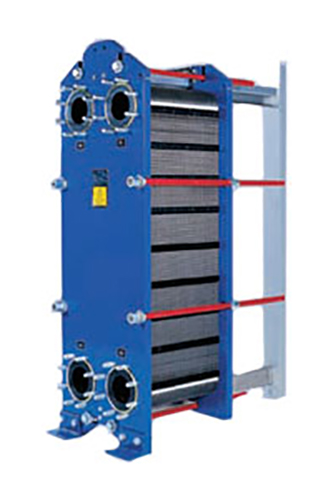
- Standard design
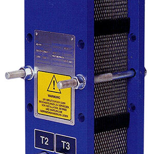
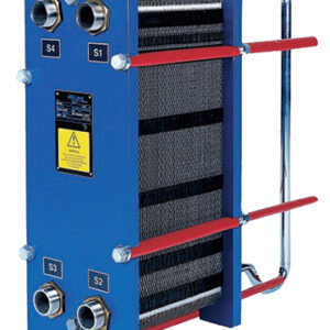
- The plate heat exchanger consists of a pack of corrugated metal plates with portholes for the passage of the two fluids between which heat transfer will take place.
- The plate pack is assembled between a fix frame plate and a movable pressure plate and compressed by tightening bolts. The plates are fitted with a gasket which seals the interplate channel and directs the fluids into alternate channels. The number of plates is determined by the flow rate, physical properties of the fluids, pressure drop and temperature program.
- The plate corrugations promote fluid turbulence and support the plates against differential pressure. The plate and the pressure plate are suspended from an upper carrying bar and located by a lower guiding bar, both of which are fixed to a support column.
- Connections are located in the frame plate or, if either or both fluids make more than a single pass within the unit, in the frame and pressure plates.
Typical capacities
- Liquid flow rate
- Up to 80 kg/s (1300 gpm), depending on media, permitted pressure drop and temperature program.
- Plate types
- M15B, M15E, M15M and M15BD
- Frame types
- FL, FM, FG and FD
Working principle
Channels are formed between the plates and the corner ports are arranged so that the two media flow through alternate channels. The heat is transferred through the plate between the channels, and complete counter-current flow is created for highest possible efficiency. The corrugation of the plates provides the passage between the plates, supports each plate against the adjacent one and enhances the turbulence, resulting in efficient heat transfer.
| Flow principle of a plate heat exchanger |
STANDARD MATERIALS
Frame plate
Mild steel, Epoxy painted
Nozzles
- Carbon steel
- Metal lined: Stainless steel, Titanium
- Rubber lined: Nitrile, EPDM
Plates
- Stainless steel: Alloy 304, Alloy 316
- Titanium
- Alloy C-276
- Alloy 254 SMO
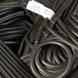
Gaskets ( Clip-on/tape-on, glued)
| M15B | Nitrile, EPDM, HNBR, EPDMF, Viton®G, AL-EPDM |
| M15M | Nitrile EPDM, HNBR, EPDMF, Viton®G, AL-EPDM |
| M15E | Nitrile |
| M15BD | Nitrile, EPDM, VitonRG, HNBR |
TECHNICAL DATA
Pressure vessel codes, PED, ASME, pvcALS™ Mechanical design pressure (g) / temperature
| FL | pvcALS™ | 0.6 MPa / 130°C |
| FM | PED, pvcALS™ | 1.0 MPa / 180°C |
| FG | PED, pvcALS™ | 1.6 MPa / 180°C |
| FG | ASME | 150 psig / 356°F |
| FD | PED, pvcALS™ | 3.0 MPa / 180°C |
| FD | ASME | 300 psig / 356°F |
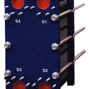
CONNECTIONS
| FL | pvcALS™ | Size 150 mm | DIN/GB/GOST PN10, ASME CI. 150, JIS 10K |
| FM | PED | Size 150 mm | DIN 2501 PN16, ASME CI. 150 |
| FM | pvcALS™ | Size 150 mm | DIN/GB/GOST PN10, ASME CI. 150, JIS 10K |
| FG | PED | Size 150 mm | DIN 2501 PN16, ASME CI. 150 |
| FG | pvcALS™ | Size 150 mm | DIN/GB/GOST PN16, ASME CI. 150, JIS 16K |
| FG | ASME | Size 6″ | ASME CI. 150 |
| FD | PED | Size 150 mm | DIN 2501 PN25, ASME CI. 300 |
| FD | ASME | Size 6″ | ASME CI. 300 |
Dimensions
Measurements mm (inch)
| Type | H | W | h |
|---|---|---|---|
| M15-FL | 1815 (71 1/2″) | 610 (24″) | 275 (10 3/4″) |
| M15-FM | max. 1941 (76 1/2″) | 610 (24″) | 275 (10 3/4″) |
| M15-FG | max. 1941 (76 1/2″) | 650 (25 1/2″) | 275 (10 3/4″) |
| M15-FD | max. 2036 (80″) | 650 (25 1/2″) | 370 (14 1/2″) |
The number of tightening bolts may vary depending on pressure rating.
Maximum heat transfer surface
390 m2 (4200 sq. ft)
Particulars required for quotation
- Flow rates or heat load
- Temperature program
- Physical properties of liquids in question (if not water)
- Desired working pressure
- Maximum permitted pressure drop
- Available steam pressure